Reverse engineering the Apple M1 Bluetooth interface
Back in April of 2022, I reverse-engineered the interface that drivers use to communicate with the Bluetooth module on Apple M1 machines so that Asahi Linux could support Bluetooth on these devices. I documented the results in a prototype driver that was written in Python and ran in userspace. By July, other members of the Asahi team had written a real driver that is now shipping to end users.
In this post, I will document the thought processes that went into this reverse engineering effort. Unfortunately, I experienced a hardware failure in the meantime and don't have my old annotated reverse engineering notes, so this will be done on a best-effort basis.
Background
Unfortunately, this post cannot be an introduction to reverse engineering as a whole. Reverse engineering is an extremely broad topic with many areas to cover, including
- assembly language and the AArch64 instruction set. The official documentation for the AArch64 instruction set can be found here.
- operating systems. It is extremely useful to have a general idea of how operating systems work and are designed, but, as I will show here, a detailed knowledge of macOS internals is not specifically required. I have gotten away with consulting the official IOKit documentation only when needed, figuring things out as I go along.
- educated guesswork. Lots of guesswork. Having a vague idea about how other systems work and are designed helps when reverse engineering an unknown system. There are many common patterns (e.g. ring buffers, doorbell registers, firmware loading) that occur throughout different systems, and having this knowledge available to hand makes guessing much faster and more efficient.
Initial reconnaissance
One of the first things to do when reverse engineering a system is to have a poke around in order to gather information. The first tool I personally reached for was IORegistryExplorer, which is available as part of the "Additional Tools for Xcode." This tool displays information used by macOS device drivers.
The first thing I did was to open IORegistryExplorer, select the IODeviceTree "plane" (I didn't read the documentation enough to know what exactly a plane is, but I did know from previous efforts that this plane matches the Apple Device Tree information that m1n1 can dump), and search for "bluetooth".
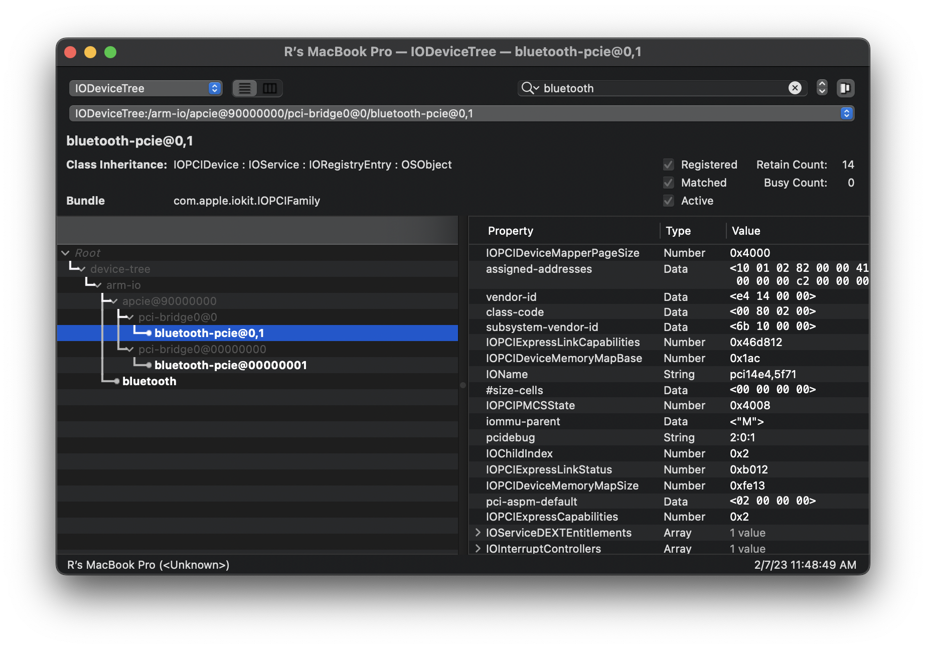
This immediately tells me some information:
- Bluetooth is running over PCIe. There isn't a standard way of doing this according to the Bluetooth Core specification (we will need this document again later), but the commands running on top of the PCIe link might still be standard (we do not know yet at this point).
- Bluetooth is a second PCIe function on the same device as WiFi. This can be seen from the
0,1address (as well as by runninglspciwhen booted into Linux).
Repeating the same search on the IOService "plane" results in the following hierarchy:
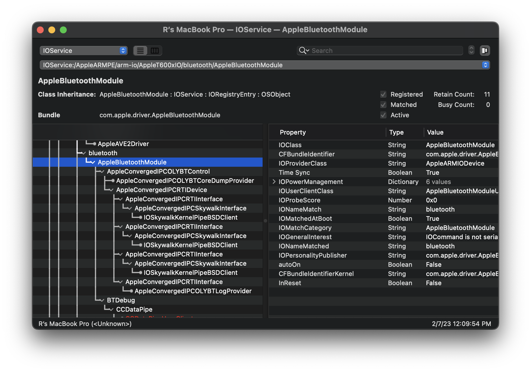
Some quick research online seems to hint that this may be an Apple-specific interface (most WiFi+BT cards in mini-PCIe form factor use USB for the Bluetooth function). At this point, my preference is to jump in to static analysis.
Static analysis
I began static analysis by loading AppleBluetoothModule and AppleConvergedIPCOLYBTControl (visible in IORegistryExplorer), as well as the similarly-named AppleConvergedPCI as a guess, into Ghidra. These drivers can be found inside /System/Library/Extensions of a macOS install. Interestingly, when loading these drivers, Ghidra informs us that they are "fat binaries" containing both x86_64 code as well as AArch64 code. It turns out that some of the latest x86 Macs also have a similar Bluetooth module connected over PCIe, and this reverse engineering work is applicable for them as well.
The first thing I do when loading a macOS driver into Ghidra is to look at the class and function names. These are usually not obfuscated and give a good overview of what the code might be doing. Some of the functions in AppleBluetoothModule look like this:
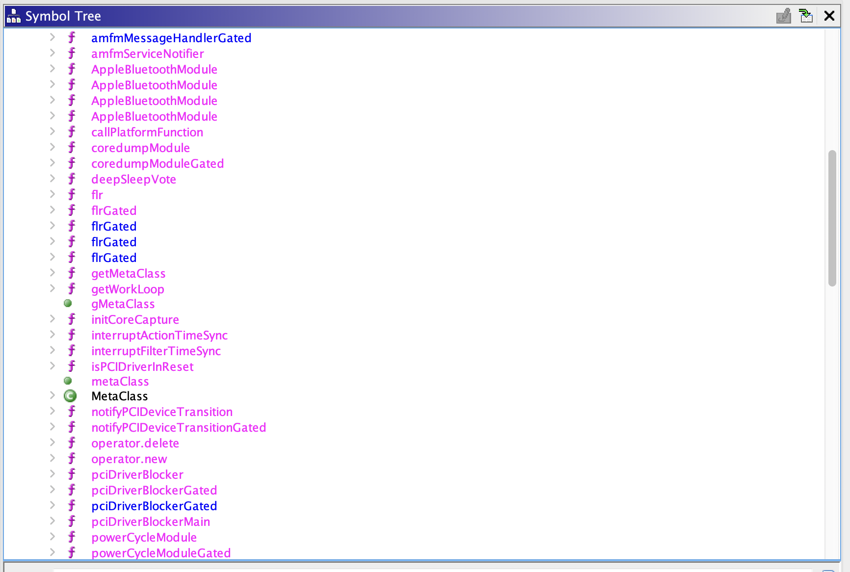
My initial impression was that this code seems to be used for "gluing together random bits related to PCIe" and was not related to "actually talking to the chip," so I quickly moved on to AppleConvergedPCI instead:
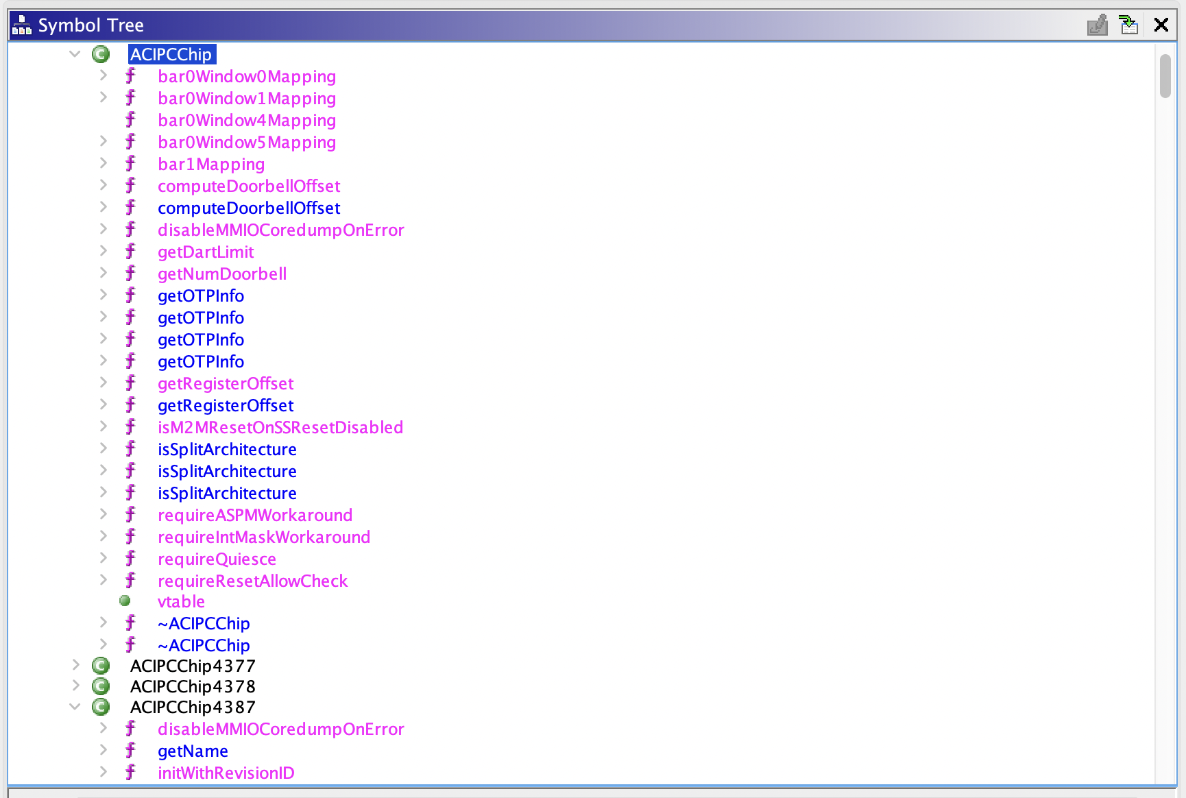
Ah! At this point I know I'm in the right place because I can see familiar numbers! (It's not visible in the screenshot above, but the device tree in IORegistryExplorer contains a "compatible" string of wlan-pcie,bcm4387). One function immediately jumps out to me: getRegisterOffset
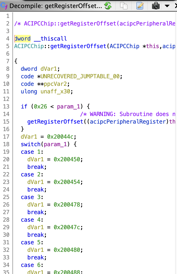
We don't yet know what any of these registers do, but the fact that they've been wrapped in this layer of indirection means that most likely either these registers are the only registers the driver accesses, or they're at least the most important ones. We can quickly note these down in a "notes" file.
Nothing else in AppleConvergedPCI seemed to be doing anything particularly interesting, so we move on to AppleConvergedIPCOLYBTControl.
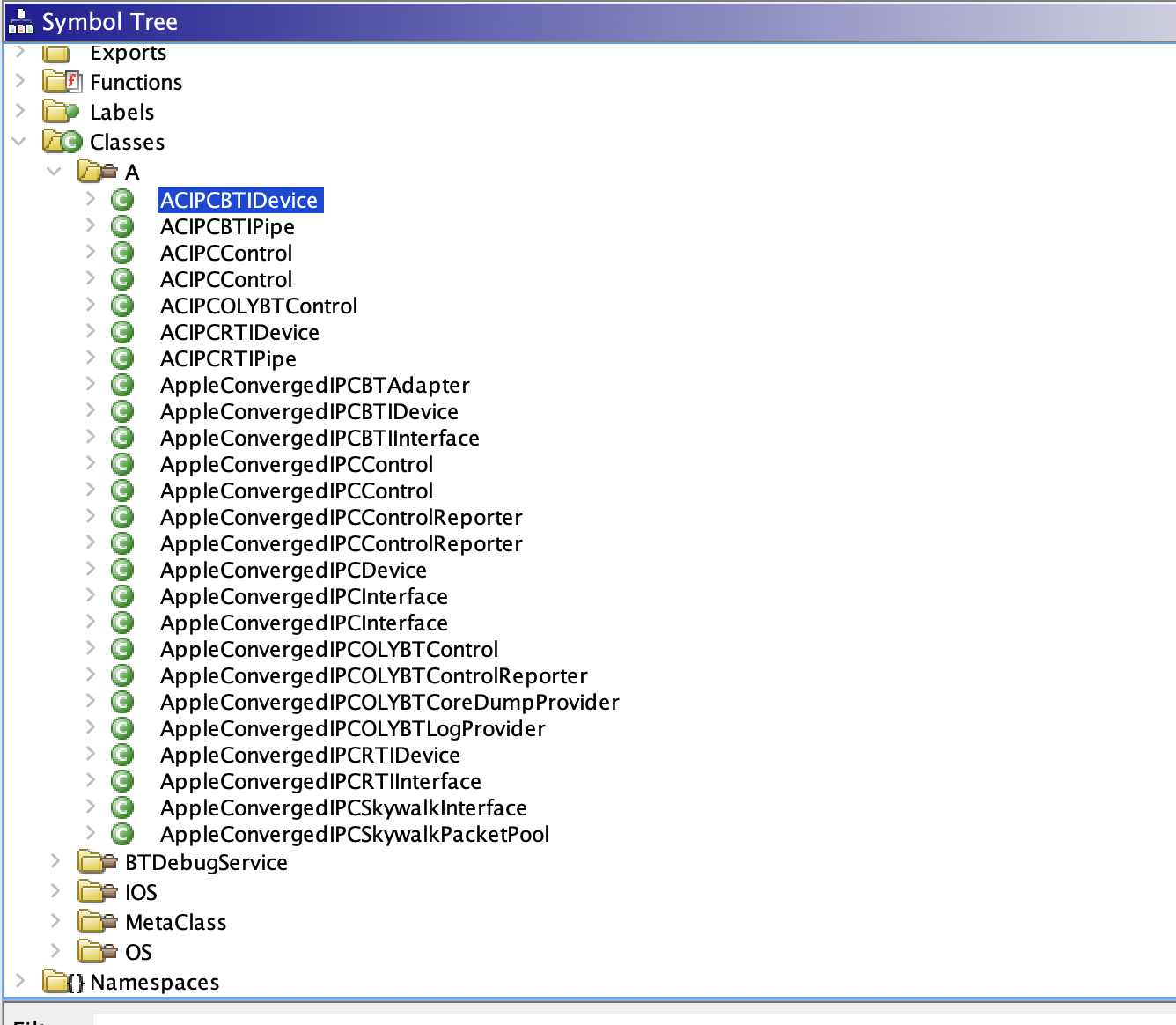
Jackpot? Based on the amount of code in here, as well as the names in IORegistryExplorer, this is almost certainly the bulk of the driver logic. At this point, it's time to perform a bunch of the static analysis Sudoku puzzle. It's hard to describe step-by-step how this process works, but the gist of it is:
- Find something you don't understand, but where you understand most of the surrounding pieces.
- Figure out what it does.
- Repeat until you understand everything.
Initial static analysis notes
The first thing I noticed was the separate set of classes containing "BTI" vs "RTI". Since I expect that this card probably requires firmware (just like the WiFi function does), I take a wild guess that "BTI" might stand for "boot-time interface" and that "RTI" might stand for "run-time interface". This is backed up by the fact that "BTI" mostly only seems to be able to "send an image" while "RTI" does a lot of work with things like "MR" "CR" "TR" "CD" etc.
When reverse engineering C++, it is extremely helpful to properly define all of the classes in the Ghidra structure editor. In order to figure out the sizes of some of these classes in bytes, I look for calls to the constructor and then look for the preceding calls to __Znwm (the global operator new):

In this case, the size of the ACIPCBTIPipe object is 0x30 bytes.
In other cases (mostly classes that are more involved with IOKit), the class itself will contain an operator new method that calls into _OSObject_typed_operator_new:
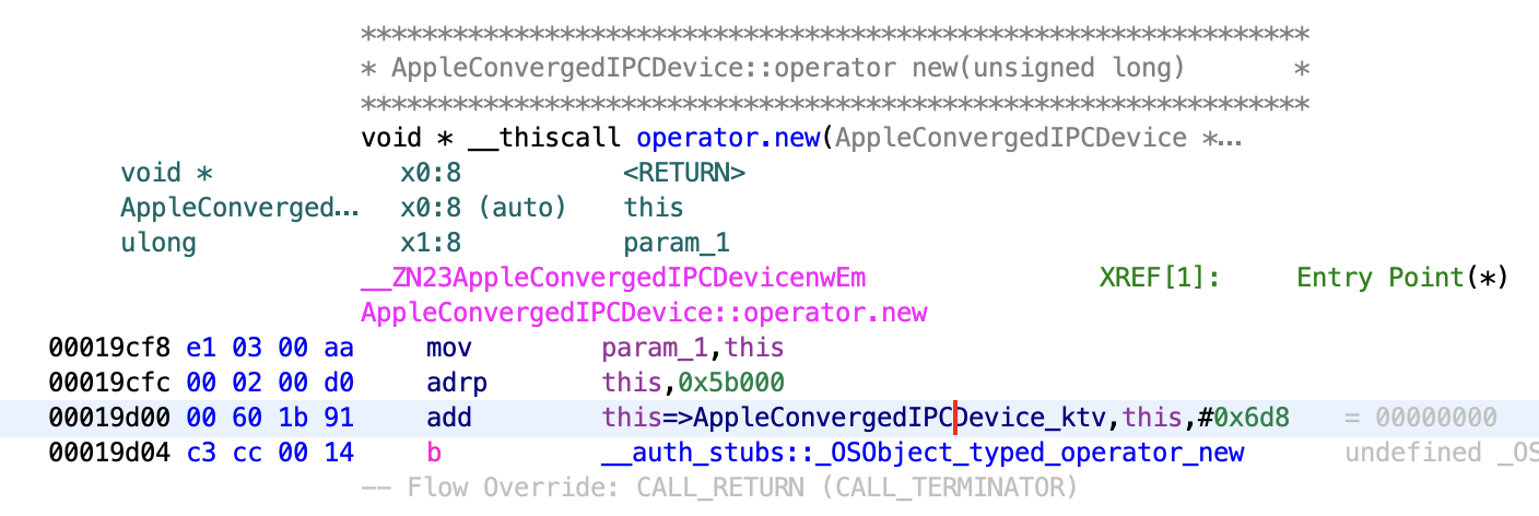
Understanding this requires digging through the XNU source code a bit to find the size.
Once a few classes have been briefly annotated, the function of some of the registers starts to become clear. For example, here's a fragment from the ACIPCBTIDevice::updateImageAddr method:
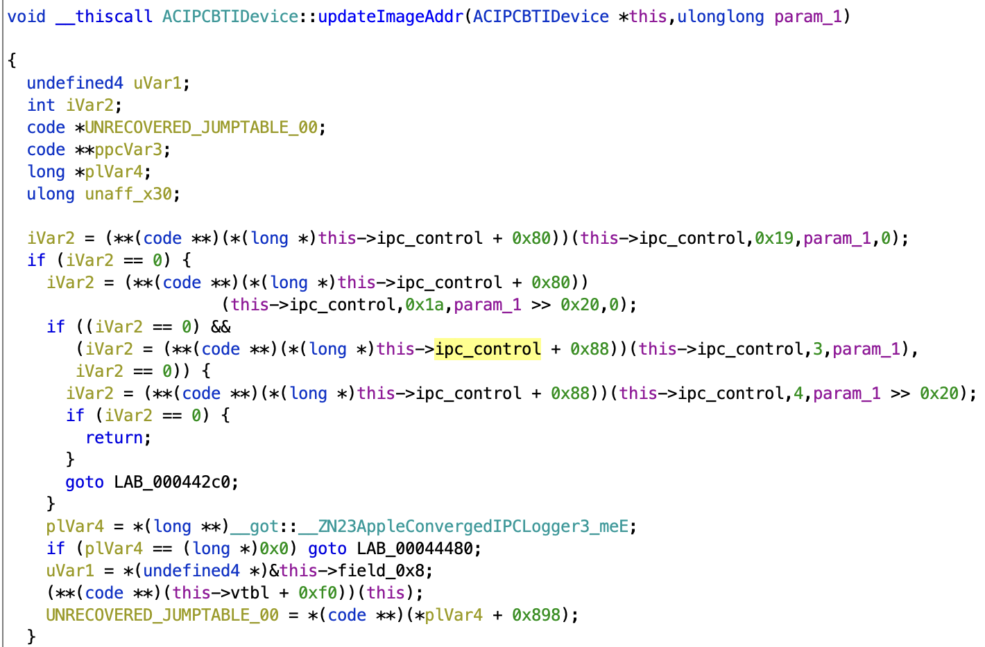
The + 0x80 and + 0x88 vtable calls are ACIPCControl::writeBar0Register and ACIPCControl::writeBar1Register respectively, which are defined back in the AppleConvergedPCI driver (I do not know a convenient way to annotate vtables in Ghidra and usually follow them manually). This shows that the BTI "image" (which we are guessing is firmware, but have not yet confirmed) address is written to registers 0x19/0x20 and 3/4. Some further reverse engineering following the same reasoning finally yields an initial register list like in this commit.
Finally, various "debug" and "state dump" functions often provide useful hints, such as this method ACIPCRTIDevice::stateDump:
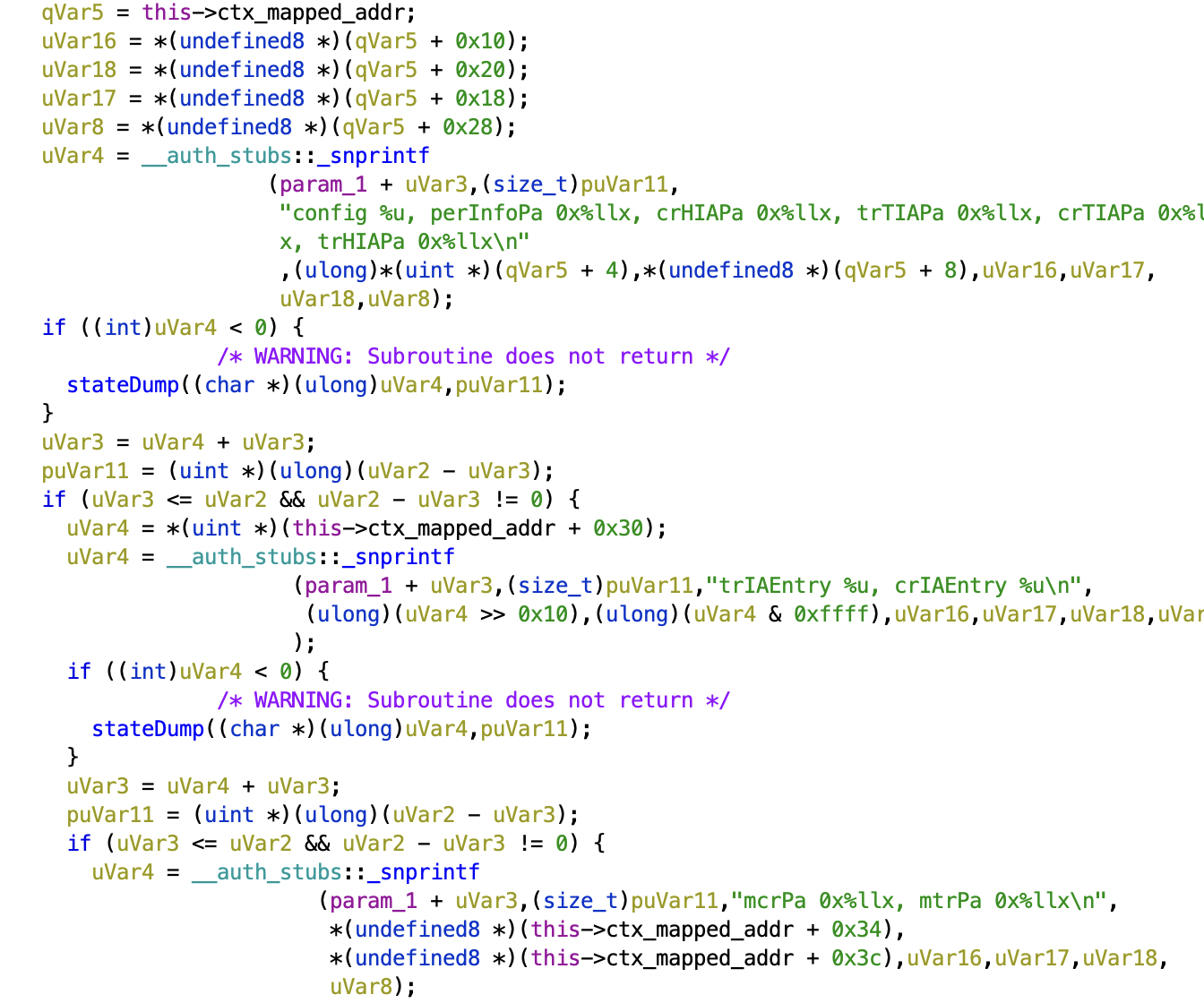
However, although this code may give the names of fields in a structure, it is not 100% clear exactly what these RTI-related structures are used for, and it eventually becomes easier to supplement static analysis with dynamic analysis.
Switching to tracing and dynamic analysis
In order to switch to dynamic analysis and trace what macOS is doing, we make use of m1n1's hypervisor. When this effort was first being performed, there was no code to help with tracing PCIe devices, so I wrote a tracer that hard-codes the physical addresses that the Bluetooth device PCIe BARs get mapped to. This was "good enough" to get initial reverse engineering done.
By dumping the "image" that is initially sent to the card (code here) and then comparing it against files in /usr/share/firmware/bluetooth, we can confirm that this first stage is indeed a firmware load done by the "BTI" classes. We can also dump the "context" set by ACIPCRTIDevice::updateContextAddr and confirm that it matches the structure printed by ACIPCRTIDevice::stateDump (this code is here).

At this point, a very tedious back-and-forth process occurs of updating the tracer based on static analysis findings, and then updating the static analysis based on the tracer results. The first significant milestone is uncovering the ring buffer used for control messages on pipe 0 (code here).

The tedious back-and-forth repeats again, but I start noticing that a lot of the settings that go into these control messages seem to come from Somewhere™ that I don't understand. Eventually, in a flash of insight, I open /System/Library/Extensions/AppleConvergedIPCOLYBTControl.kext/Contents/Info.plist and discover:
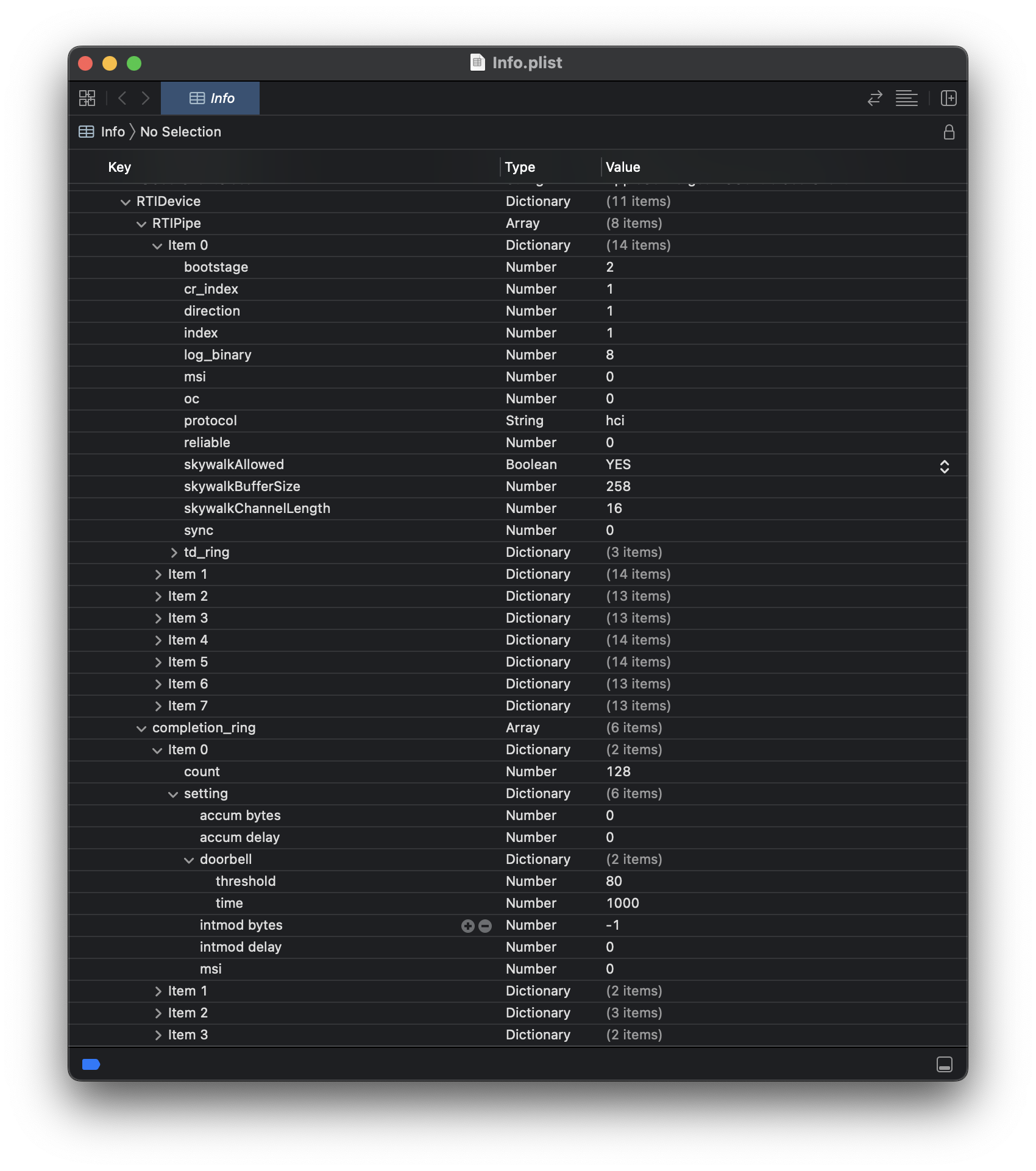
... oh. Sometimes it helps to read the documentation. Reading through this plist file, we discover that it references separate pipes for "HCI", "SCO", "ACL", and "debug". I don't know what any of these terms are, but a quick poke through the Bluetooth Core specification reveals this table in the section describing the UART transport layer:
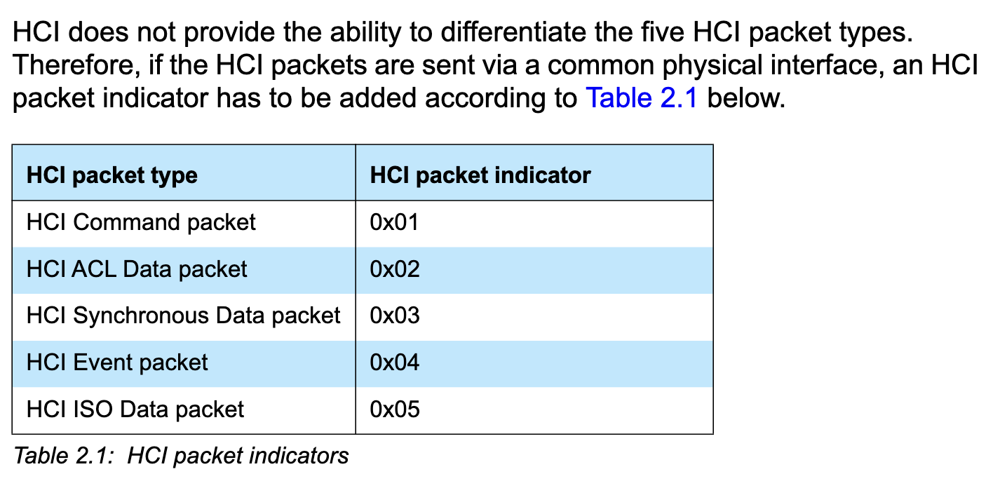
This is starting to make sense. Instead of adding a byte prefix like the UART transport layer, Apple seems to have separated out each type of Bluetooth packet into a separate "pipe" with its own ring buffers, and the plist specifies how these are all tied together.
The reverse engineering process proceeds until the tracer can dump HCI commands as well as their corresponding responses. This finally results in this Tweet showing command 0x1002 Read_Local_Supported_Commands in the TR and the corresponding reply in the CR. From the dumps, we can confirm that this Bluetooth adapter does indeed still use standard HCI commands, just wrapped in this Apple-specific transport.
After tracing data flowing through in both directions, we can finally make reasonable guesses as to what various abbreviations in the driver codebase mean:
- HIA - head index A?
- TIA - tail index A?
- CR - completion ring
- TR - transfer ring
- MR - message/management ring
- TD - transfer descriptor
- CD - completion descriptor
It's time to be brave and try driving the device ourselves with our own driver!
Prototyping a new driver
In order to prototype a driver quickly, I wanted to be able to use a high-level programming language that's extremely convenient for rapid prototyping, such as Python. Most of the other Asahi experimentation is already done with Python scripts running on a separate computer interfacing with m1n1. However, there weren't any examples of how to set up a PCIe device under m1n1, and I didn't want to invest a lot of effort into making that work. Fortunately, Linux already has functionality for writing userspace PCIe drivers — VFIO. VFIO is well-known for allowing "passthrough" of PCIe devices from a hypervisor host to virtual machines, but it also allows safe (IOMMU-protected) access to PCIe devices from userspace.
I start putting together a Python skeleton to poke BAR registers interactively while booted into Linux. However, I quickly discover an issue — accessing some registers (e.g. CHIPCOMMON_CHIP_STATUS) works, but accessing most registers cause the entire machine to lock up and eventually watchdog reboot. This happens even if I access them in the exact same sequence as macOS does. Much frustration ensues.
Eventually, I start using the debugging technique of "what information do I have that I have not used yet?" One obvious piece of information is the AppleConvergedPCI driver and the ACIPCChip43XX classes, all of which seem to just initialize some magic numbers and then not do anything else. While thoroughly combing through this driver (and continuing to bang my head against the desk), I eventually notice AppleConvergedPCI::setupVendorSpecificConfigGated
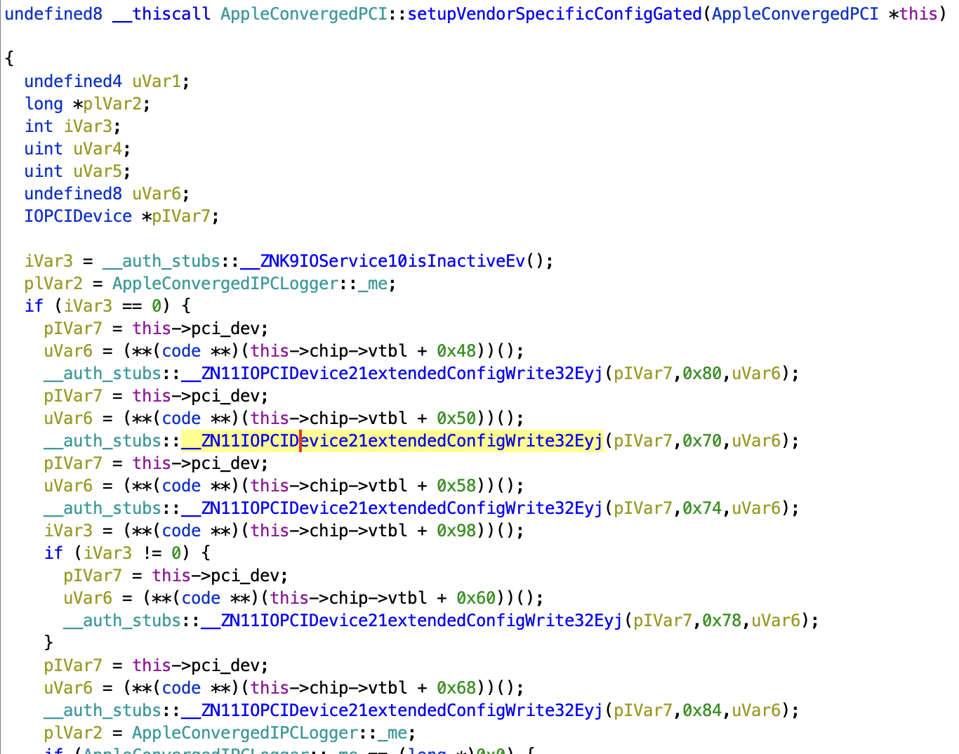
PCIe config space. Of course. Since the PCIe configuration space is not part of a BAR, none of my tracing captured it. It's also the perfect location to put magic pokes that completely change how the rest of the chip behaves. This also explains what the magic numbers in ACIPCChip43XX are for — they are written into the configuration space to change what is mapped into the memory BARs. This also explains why not setting them up causes a system lockup — accessing an invalid/unmapped address. Pasting these pokes into my Python driver and... success! I can read/write registers without crashing. From there, it's a very quick bit of code until I can successfully boot the firmware.
Once the firmware is booted, I just need to set up the RTI "context" data structure, and then I can transition the firmware into state 1 followed by state 2 where it should be running (code here).
From here, further iteration and experimentation gets to the point where completion rings can be opened followed by opening transfer rings. At this point, we can now manually send Bluetooth HCI commands via the Python interactive shell.
The macOS kernel driver does not handle higher-level concerns such as calibration (deferring these to userspace). However, in order to make this work under Linux, we have to do this functionality ourselves. The m1n1 tracer is now complete enough to show that the relevant commands are 0xFD97 to load calibration and 0xFE0D to load a "PTB" (both within the vendor-specific command range). In the prototype, we duplicate the commands here. At this point, I can finally send 0x0C1A Write_Scan_Enable via the Python interactive shell and get this Tweet where an Android phone is detecting the M1.
Fleshing out the prototype driver
After getting HCI commands working via an interactive shell, the next logical step is to try to integrate it with the rest of the Linux Bluetooth stack. Fortunately, Linux once again has a good mechanism for doing this — Bluetooth VHCI. There doesn't appear to be any documentation about how this is supposed to work, but the interface happens to be straightforward enough (open /dev/vhci and then read/write packets prefixed by a byte indicating HCI packet type).
Quickly hooking this together yielded this Tweet showing the M1 laptop scanning and detecting an Android phone, with everything already correctly plumbed through all the way to the GUI layer.
At this point, I attempt to support SCO data, but it uses a different doorbell mechanism and immediately causes an interrupt storm. I set this aside and decide to come back to it later (this is always a valid approach!). I instead decide to tackle ACL data, which requires me to figure out how the sharing of completion rings works. I try to test using command 0x1802 Write_Loopback_Mode, only to discover that it appears to be broken or otherwise somehow crashes the firmware. Undeterred, I decided to just plow forwards and integrate ACL experiments directly into the VHCI logic.
While experimenting with this, I compared against multiple traces I had captured from macOS and eventually discovered the following major quirk: when ACL data to the host fits inside the completion ring, the buffer passed in the transfer ring is not used. The buffer in the transfer ring is only used when the data is too large to fit directly inside the completion ring. (There are flag bits in the descriptor that indicate this.) Once this was correctly handled, I posted this Tweet where I successfully sent a file via OBEX to a phone.
However, it was clear that there was still a bug. Implementing analogous handling of larger ACL buffers going out to the adapter was sufficient to finally fix that as well (after resetting multiple pieces of software repeatedly as they got confused by bogus data). With that, pairing and playing audio via A2DP worked!
Finally, I re-enabled the SCO logic I had set aside (and ignored the resulting interrupt storm). This appeared to also work, so I declared the prototype "complete enough," wrote a README, and announced it publicly.
Aftermath
Eventually, sven from the Asahi project took on the effort needed to turn this prototype into a real driver. For the most part, this was a fairly straightforward affair. However, some further discoveries were made along the way:
- several of the unknown register writes (e.g.
REG_21andREG_24) in my prototype can just be ignored with seemingly no effect - treating the SCO doorbell as... not special causes the interrupt storm problem to go away
- the details of reading the chip ID, revision, and OTP were figured out in order to select the correct firmware
- the adapters use reserved bits to indicate the channel of received BLE advertisements. This helps explain why BLE did not work in my testing with my prototype.
- quirks specific to the 4377 and 4378 chips were figured out
But, with all of that sorted, the driver has made its way upstream!